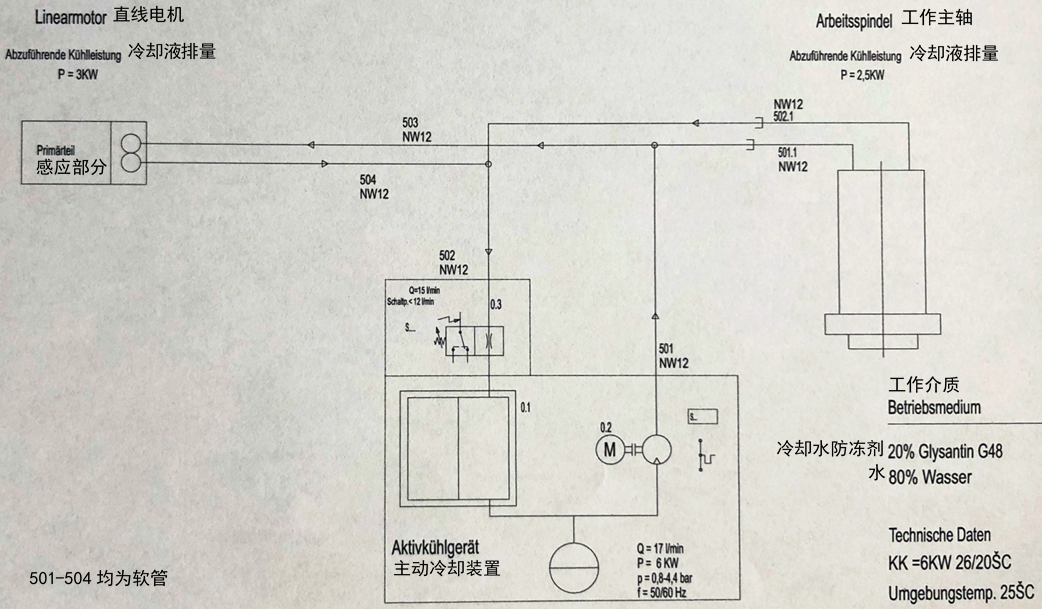
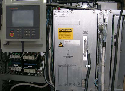
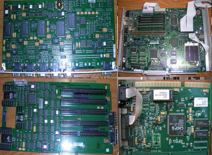
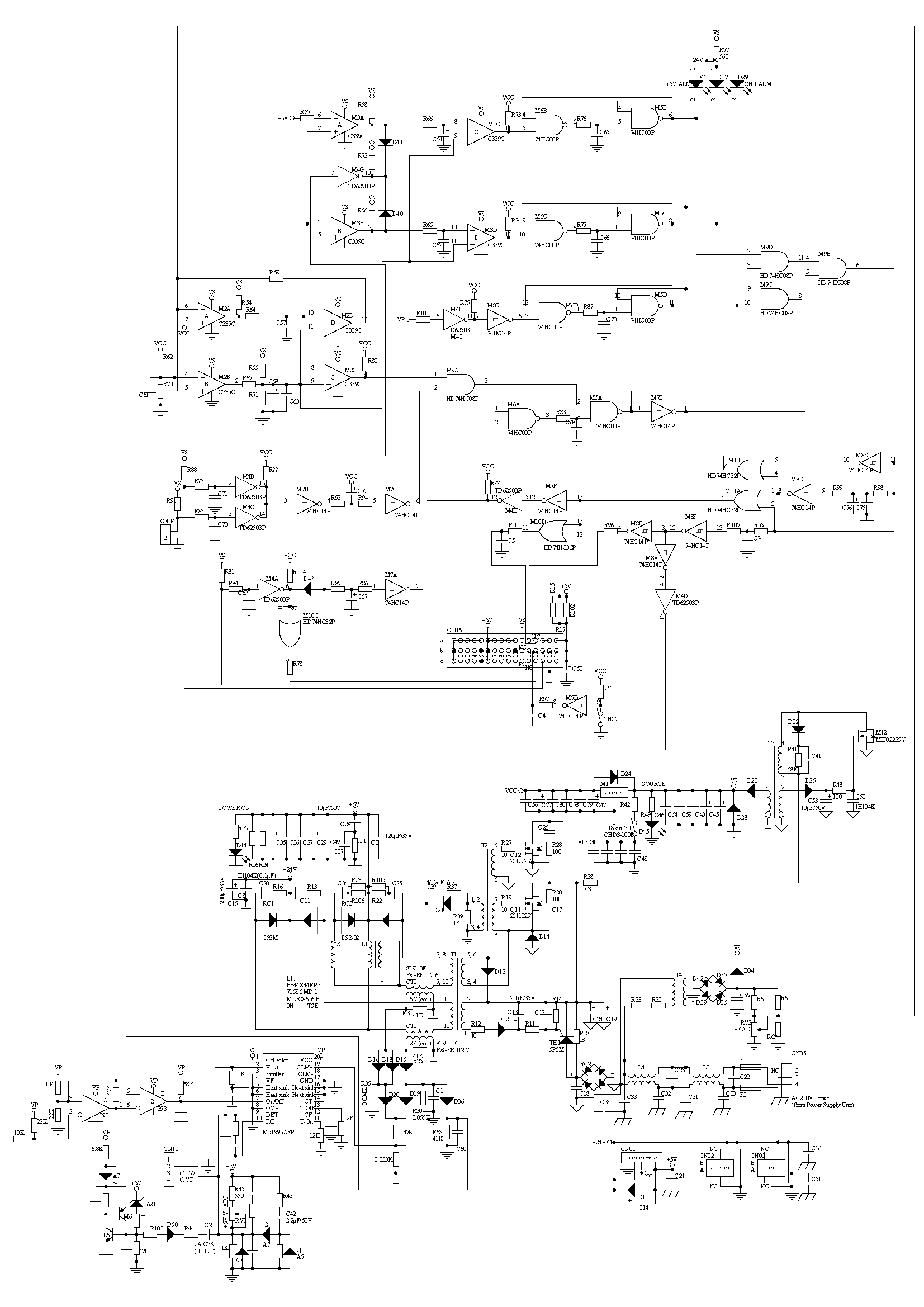
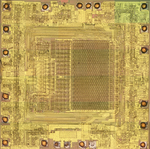
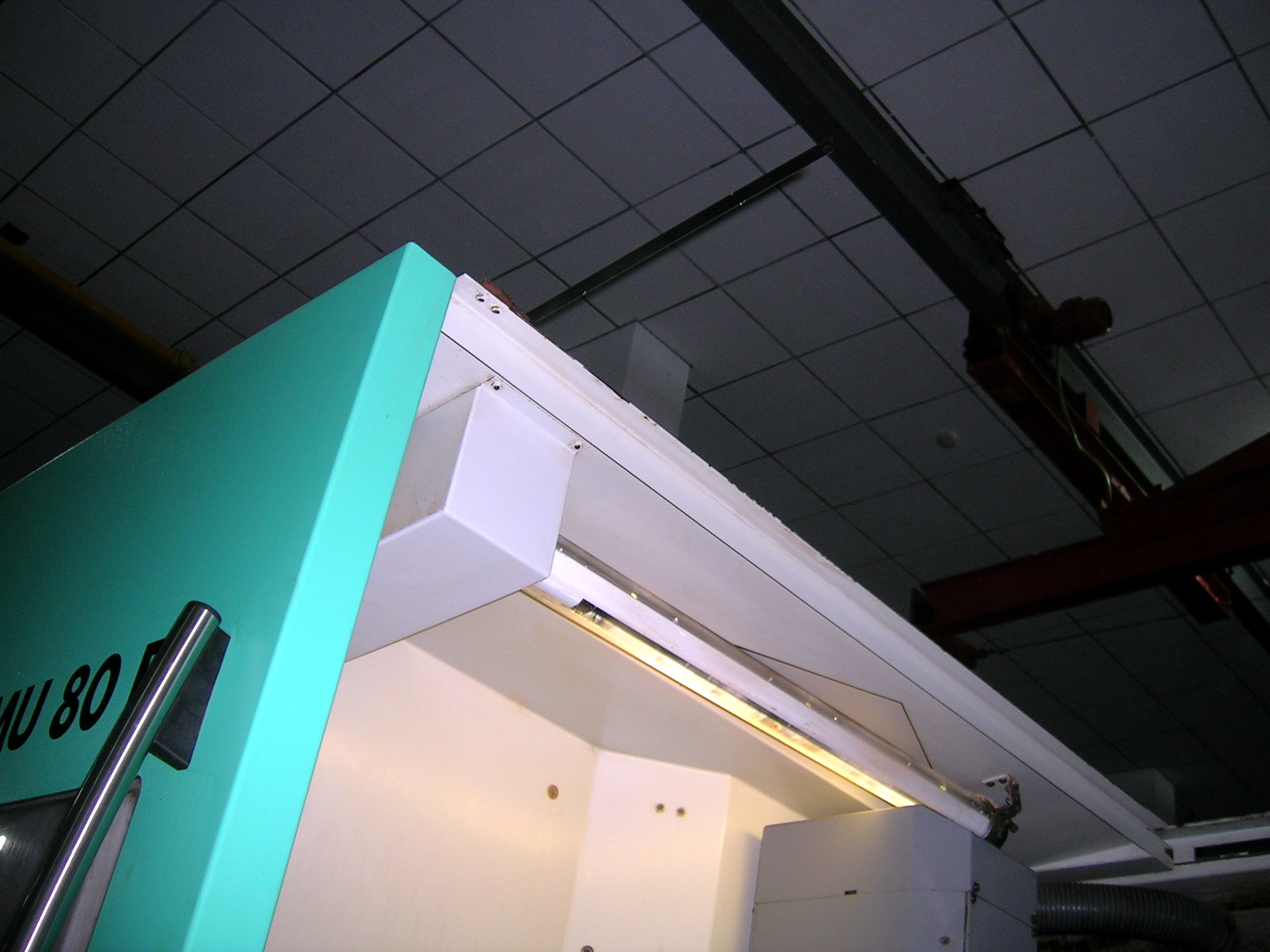
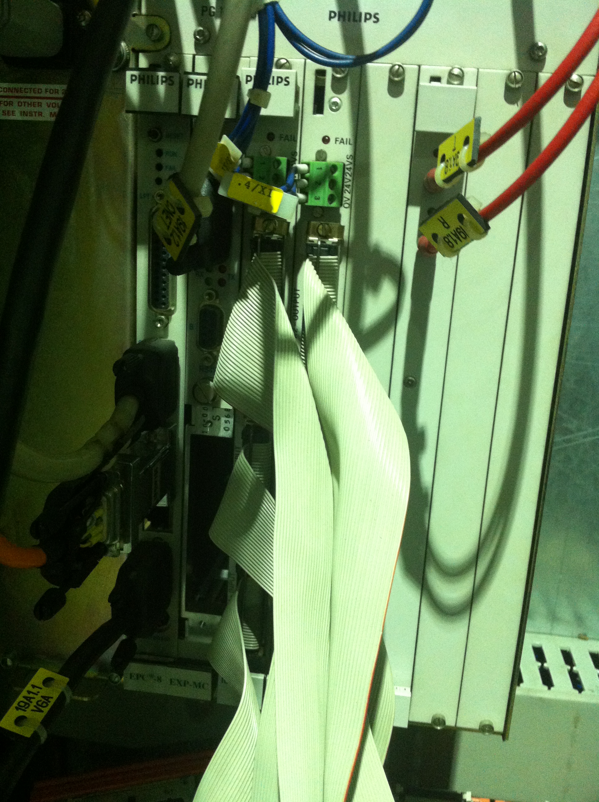
A (cromatic) 2100 CNC control (Fig.1) is a product of Vickers company in the United States in the late 1990s, which is a so-called PC based CNC system. Its hardware is mainly composed of the left main board (usually Intel 486 general-purpose computer motherboard with a 500M hard disk, which is responsible for the system software and hardware operation, called Workstation Board), the right main board (also a general computer motherboard, for real-time processing, called Realtime Board), Bridge Board (which is the interface of the boards and cards, the main control chip is an Intel MCS 51 series single-chip microcomputer), Servo Board (the interface between the system and the servo module of each axis, which is also a 51 series single chip computer application system), I/O Board (programmable logic application circuit, I/O interface of machine tool), etc. The software is an application program loaded automatically on Windows NT platform when startup.

(1) Appearance of control (2) System boards
Fig. 1: Vickers A2100 CNC system
Given based on PC, the repair will be more convenient and the cost can be reduced. For example, the hard disk can be replaced by a general hard disk and hung to the desktop for backup or check. However, the slot connection between the boards and cards is easy to cause poor contact. During maintenance, the pull-out should be reduced and the electrical cabinet should be kept clean. If necessary, the electrical cabinet can be separated from the bed to reduce vibration, and the electrical cabinet can be equipped with air conditioning to maintain the stable and suitable temperature.
The following is a brief description of the repair methods and examples, of course only for those A2100 machine tools.
1 System troubleshooting
This category includes system board, hard disk, display, serial communication, etc. Many faults are caused by poor contact of connectors. It is necessary to judge calmly during maintenance, and do not dismantle and replace at will. It should be noted that the system hard disk should be backed up as soon as possible, otherwise it will be difficult to recover in case of hardware and software failure. The backup method is the same as that of general computer hard disk, but great care should be taken. The setting and initialization of hard disk partition, the selection of operating system and backup software are very important. The wrong backup method will make the original normal hard disk inaccessible.
Ex. 1 A SABRE1250 screen did not display, inspection showed that the relevant connectors were normal. Checked to find that FU5 was burnt out. After replacement, powered on, the fault was still there, and FU5 was burnt out again. According to the circuit diagram, the fan of Y-axis servo module was found to be damaged and the machine tool returned to normal after replacement.
Ex. 2 A SABRE1000 always stopped at the following text line when starting up:
AMIBIOS (C) 1999, American Megatrends, Inc.
BIOS Version: 1.00.05.AZ0
016384 KB
Please Wait…
Keyboard……Not Detected
After eliminating the possible bad contact of the hard disk, replaced the disk with a backup, and the fault disappeared. Another example also stayed on the page, but there was a more line of text: Drive not ready error. Here “drive” means hard disk drive, not floppy disk drive even servo drive module. If this is well understood here, it is easy to solve the problem. Pulled out and pushed in the hard disk connectors again, the boot became normal.
Ex. 3 When a SABRE1000 started to boot windows (in the startup screen, it is normally Vickers logo with light blue and green background), the display was out of order. In the previous text screen, the date and time in CMOS were hinted not set, so it was suspected that the CMOS parameters of the left motherboard were missing. Replaced the button cell battery (had been low) and cleared corrupted CMOS data. Connected an external keyboard (cable lengthened) to set the CMOS parameters following a backup. Restarted the control and the machine tool returned to normal.
Ex. 4 The 8004d red alarm appeared in a SABRE1000, which means that the workstation message service program cannot receive the response signal from the real-time processing module. Pressed the “Reset system” key, the system became normal after restart. However, when the magazine returned to the reference point, the alarm appeared again. Turned off the machine and separated the right main board and plugged it in again and the fault disappeared.
Ex. 5 when a SABRE1000 booted, 8004e red alarm appeared, which means that the power supply of control is abnormal, so as to make the real-time processor reset and restart. Cleaned the connectors to make the contact reliable and tried to reset, switch on and off for many times. But the fault persisted. In order to facilitate repair, replaced the power supply module directly and the machine restored to normal immediately.
The power supply module can be replaced by ordinary computer power supply. If similar products cannot be found, just buy a new one on the market and modify the connectors slightly.
Ex. 6 The alarm page appeared after a SABRE1000 was turned on:
Name Part Number # Result
Bridge Board [WS] 3-542-1260A+ 1 Failed
Bridge Board [RT] 0 Unknown
Conv. Servo 0 Unknown
High Density I/O 0 Unknown
Pendant/Panel [MSL] 0 Unknown
Realtime Processor 0 Unknown
Keypad/Touch Screen 3-542-1223A.B 1 Passed
Workstation Processor 3-424-2123A 1 Passed
Obviously, the system self-diagnosis found that the bridge board was abnormal. Because the servo, I/O, etc. at the back were connected with the bridge board, so they could not be identified (unknown). In order to determine the fault, replaced the bridge board with that of a VMC1000C which worked normally, and the alarm page changed to:
Name Part Number # Result
Bridge Board [RT] 0 Unknown
Conv. Servo 0 Unknown
High Density I/O 0 Unknown
Pendant/Panel [MSL] 0 Unknown
Realtime Processor 0 Unknown
Bridge Board [WS] Unknown C 1 Passed
Keypad/Touchscreen 3-542-1223A.B 1 Passed
Workstation Processor 3-424-2123A 1 Passed
“Failed” disappeared in WS side of bridge board, and “unknown C” was caused by mismatch. But after a while, that “failed” appeared in the check again. There seemed poor contact between the left main board and the bridge board. And the bridge board of Sabre1000 could work normally when installed on VMC1000C. This further confirmed the judgement.
The original boards of the machine tool were restored and the connector between the left main board and bridge board was carefully cleaned, and the machine could now run normally.
Ex. 7 A SABRE1000 could not transfer program in DNC system, so pulled out DNC system plug from 25-hole RS232 socket on side plate of machine tool, connected a laptop computer with it directly, and tried with the communication software such as MTTTY and TERMINAL (empirical parameters: 19200/8/1). But still could not receive and send data.
Before turning to the left main board 9-pin COM1 socket and try again, it was found that one of the pins had been bent, and everything was normal after correction.
Ex. 8 The serial communication circuit of SABRE1250 motherboard was burnt out, but other functions were normal. Tried to transfer program through floppy drive, however, the floppy drive was always inaccessible at any security level (Operator/Setup/Service/Worldclass). Entered CMOS setup through an external keyboard and found the floppy drive had been disabled. Corrected it, OK.
Ex. 9 The touch screen of a SABRE1000 was in confusion. When clicked on a place with finger, the cursor arrow appeared at a symmetrical point about the center of the screen. It was normal after correction this way: hold down the CTRL and ALT keys simultaneously, and click anywhere on the screen with a finger, and a target icon will appear on the upper left corner of the screen. Click it, then it will appear in the lower right corner, and click again to finish. Another example was that the central part of the screen had no response, and so many operations could not function. Replaced it with spare to make it return to normal.
2 Repair of servo fault
A2100 system gives a more detailed diagnosis and treatment of servo fault. It is difficult to solve the problem only by replacing the module.
In addition, readers interested in chip level maintenance of servo module can refer to the following post:
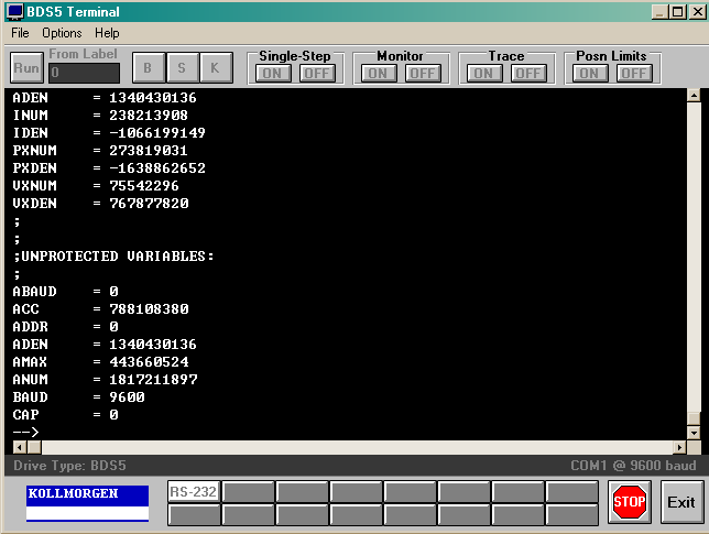
Three examples of Kollmorgen VFS5 servo repair
Ex. 10 A VMC1000C could not be powered on, and the following alarm appeared:
Alarm 40-239
Machine Not Ready
Cause: The machine has not reported a ready condition within the time limit specified by the Machine Ready configuration item.
Remedy: Check MTB machine ready conditions.
While checking the electrical cabinet, it was found that QF5 relay (I/O 24V power supply) tripped, and the alarm was eliminated after it was turned on.
Another time, the same phenomenon occurred, but QF5 did not trip. From I/O state on display knew CR_AXES_RDY (I00:00/32) signal missing. After measuring the voltage of relay pins 1604, 1704 and 506 of servo modules to ground, it was found that the relay pin of X-axis module was poorly soldered and it pulled down the voltage of CR_ AXES_ RDY. The machine was normal after re-soldering.
Ex. 11 When the X-axis of a SABRE1000 moved rapidly, there was a lot of noise in the working cabin, sometimes it disappeared and sometimes it occurred, even when it was not moving.
There is a shock absorber composed of 4 pieces of iron cake about Φ 60×10 connected to the tail of X-axis lead screw. Some looseness was found in the inspection. Dismantled the shock absorber, cleaned it, installed it again and adjusted it properly to eliminate the noise.
If it still can’t be eliminated, can adjust the STABILITY potentiometer on the X-axis module, or replace the DV5 servo board of the system, or try to exchange the X-axis and Y-axis servo modules.
Ex. 12 A SABRE1000 sometimes lost power accidentally. In serious cases, It did even when not moving or machining. The following alarm would appear on the screen:
Alarm 39-41
“Axis ready” signal missing
Cause: servo drive ready signal missing
Input CR_AXES_RDY (I00:00/32) is low level
Remedy:
Kollmorgen BDS4 drive
Check…
Could not measure CR_AXES_RDY related voltages due to random failure, so observed the machine tool for a long time while it was powered on but not machining. Later, we saw that with a sound like “Kong”, the CONTROL VOLTS indicator of Z-axis module went out, and then the contactor M20 controlling the 3-phase AC power supply of servo was disconnected. After a few seconds, the UNDERVOLTS light of each servo module was on, and then the CONTROL VOLTS indicator of Z-axis module remained off.
Seems that the interruption of the signal CR_AXES_RDY was caused by the poor contact (C3 socket and plug) of 110V AC power supply of Z-axis module or the module itself. Exchanged the C3 plugs of Z-axis and A-axis modules to change the contact state of the connectors, and the machine became normal.
Ex. 13 A SABRE1000 had the following alarm:
Alarm 39-81
Spindle not responding
Cause: A2100 system has given the spindle enable signal M1SPDL_ENBL, but did not receive the ready signal M1SPDL_READY fed back from KOLLMORGEN spindle driver.
This is still the case after the system sends the spindle reset signal.
Remedy: Check whether the “Active” indicator of spindle drive is on, and confirm that the “Fault” indicator is not on.
Check whether the spindle drive is overloaded (OVL1, OVL2).
Severity 30: Deceleration stop, data reset
It was found that the “Active” light is on, but the “Fault” light is not on, which indicates that the spindle module is normal, but the signal is not sent to the system when it is ready. Took down the plug connecting the C8 socket of the spindle module, and the plug connecting the other end to the Output Board. Plugged them back after changing the position, and the machine was normal.
Ex. 14 A SABRE1000 had the following alarm:
Alarm 39-29
The spindle does not reach the specified speed
Cause: The spindle does not reach the programmed speed within the specified time, which may be due to:
(1) The measured speed exceeds ±10% of the programmed speed
(2) No CR_SPDL_SPD signal from spindle servo module
Remedy: Observe whether the spindle is rotating, if not, check the fuse of the spindle circuit and whether the contact is poor. Observe the LED indicators of the servo module. Check whether there is poor contact from driver to CR_SPDL_SPD signal terminal of A2100 I/O card. In MDI mode, input M3S1000, use the servo display page to monitor the actual spindle speed, and compare with the programmed speed. Then observe with M4S1000. It may be necessary to adjust the spindle offset and balance and check the spindle drive configuration data.
Severity 40
Checked I/O status and found CR_SPDL_SPD signal was on.
When the programmed speed was 1000, the measured speed was less than 900, Reduced the open-loop gain, the speed was increased to the required range, and the alarm was eliminated. (on Servo Setup page, in Gain column, check Open Loop Settings option to adjust the value in the Rpm/Volt box.)
Ex. 15 A SABRE1000 had the following alarm:
Alarm 39-31
Spindle stop error
Cause: The spindle did not stop within the allowed time.
Input signals CR_ZERO_SPD and CR_SPDL_SPD should be all high.
Remedy: Check the connection of spindle driver. Check for spindle offset. Check the “Spindle and rigid tapping” option and program M3S0 in MDI mode to check the spindle offset.
Use A2100 system to balance the spindle. It may be necessary to use Motion Link software to check the drive parameters, which requires special equipment. Check the regeneration resistance of the spindle. Turn off all power before checking, because there is high voltage inside.
Close the “Spindle Setup” page before recommissioning.
Severity 40
Checked I/O status and found CR_ZERO_SPD was low level.
Under Configuration/Machine Application/Run-off Service, checked the “Spindle and Rigid Tapping Setup” option, and run M3S0 in MDI mode. Observed the spindle offset, and found that the spindle rotated at a speed of 10rpm. Appropriately increasing the value of Balance Offset Open (from +5000 to +5001 in this example) eliminated the spindle offset. However, when executing M3S1000, found that the speed increased a lot. At this time, adjusted the Open Loop Gain (in this case, to +1050 rpm/v) to make the spindle speed normal.
Ex. 16 An alarm came seconds after the power button of a SABRE1000 was pushed down:
Alarm 39-6
Axis drives not enabled
See cause (1)
Cause:
(1) Drive ready signal CR_AXES_RDY(I00:00/32) not received.
……
Severity 10: Machine powered off
Sometimes the power could be on, but after returning to the reference, moving the axes or rotating the spindle for a period of time, the alarm suddenly appeared. And sometimes other alarms successively appeared, such as “Spindle does not reach the specified speed”, “Spindle lubrication alarm”, “Spindle stop error”, “Spindle does not respond”, etc.
From the phenomenon the loss of the signal CR_AXES_RDY seems to be caused by the fault of the spindle module, which makes the three-phase AC power contactor M20 supplied to the servo power module open, so that the relays of X, Y and Z modules are disconnected. It may also be caused by poor contact.
First, checked the spindle module, and exchanged it with that on another SABRE1000. But both could work right.
No attempt was made to remove the fault one by one according to the above alarms. Checked all connectors, wiring, CR relays, etc., and no problem was found.
After a long time of exploration, it was found that after the spindle rotated for a period of time, the voltage of servo DC bus decreased gradually, especially when the speed was high (such as 2000rpm), and then the M20 contactor was broken. Thus, replaced the servo power module, and the machine tool became normal after replacement.
Ex. 17 The A-axis of a SABRE1000 had fault, it was necessary to wait for spare part. The A-axis can be easily sealed with the following method: press the setting key on the manual handle to activate the machine setting mode, and then select “REM AXIS” and “REM” to select the A-axis. At this time, the coordinate of the A-axis disappears from the screen. Select “PRES” to restore. Press “==>” and “ESC” to switch in the menu. Refer to the machine tool operation manual for the shielding method of each axis.
3 Repair of spindle lubrication fault
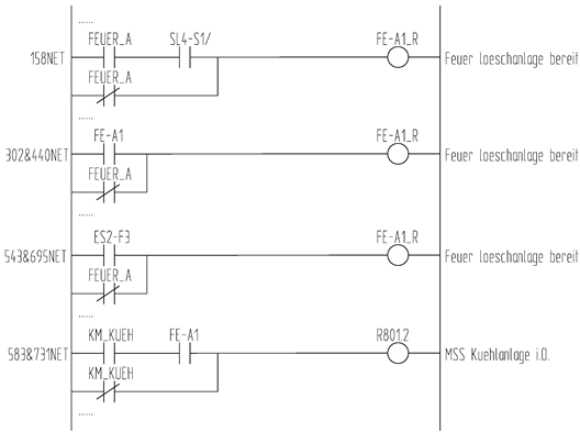
The main spindle is usually lubricated by VIP, VIP2 and other lubrication controller systems of Dropsa company of Italy, and other lubrication devices or methods are also used. But in case of failure, it is through I/O port line I00:00/33 (PS_LUBE_ALARM) to inform the CNC system. Therefore, when the spindle lubrication alarm appears on the operation screen, as long as the spindle lubrication device is checked, the problem can be solved quickly.
Ex. 18 The following alarm appeared on a SABRE1000 screen for many times:
Alarm 39-82
Spindle lubrication alarm
Cause: Dropsa spindle lubrication device alarm
Input PS_LUBE_ALARM (I00:00/33) becomes low level
Remedy: If it is VIP lubrication controller, check the status of LED indicators of the controller
Pump On yellow = pumping oil
Heathy flashing green indicates that the system is operating normally
Pump Alarm red = alarm status. Check whether the oil pressure is too low or the filter is blocked when pumping oil.
Low Level red = low lubricating oil level
Air Low red = air pressure below lower limit
Air High red = air pressure above upper limit
The nominal pressure is 2 bar. Press the red reset button to restart the oil pumping process.
If it is Dropsa advanced lubrication timer (VIP2), check the alarm diagnostic code on the display panel:
A-01 No parameters set
A-02 Oil level too low
A-03 Oil pipeline blocked, resulting in oil pressure cannot be released
A-04 Pumping is abnormal, oil pressure cannot be established
A-05 Air pressure too high
A-06 Air pressure too low
A-07 Abnormal triggering, unable to start pumping cycle
A-08 Servo motor cannot adjust air pressure
Refer to the manufacturer’s documentation for more information.
The alarm information clearly shows the maintenance method. In this case, VIP lubrication controller was used. The Pump Alarm light was on and could not be eliminated by pressing the red reset button for many times. After cleaning the oil tank, pump and filter, the alarm was gone.
Ex. 19 When the spindle of another SABRE1000 rotated, No. 39-82 (see Ex. 18) alarm appeared on the screen. This machine used VIP2 lubrication controller, and the alarm number was A-07.
Looking at the VIP2 technical document, we know that A-07 alarm will be generated in the step (SEP) mode. Changed parameter 1 from “3” to “1”, or to single line injection mode 1 (PS1), the alarm disappeared.
4 Precision adjustment
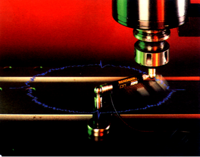
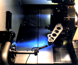
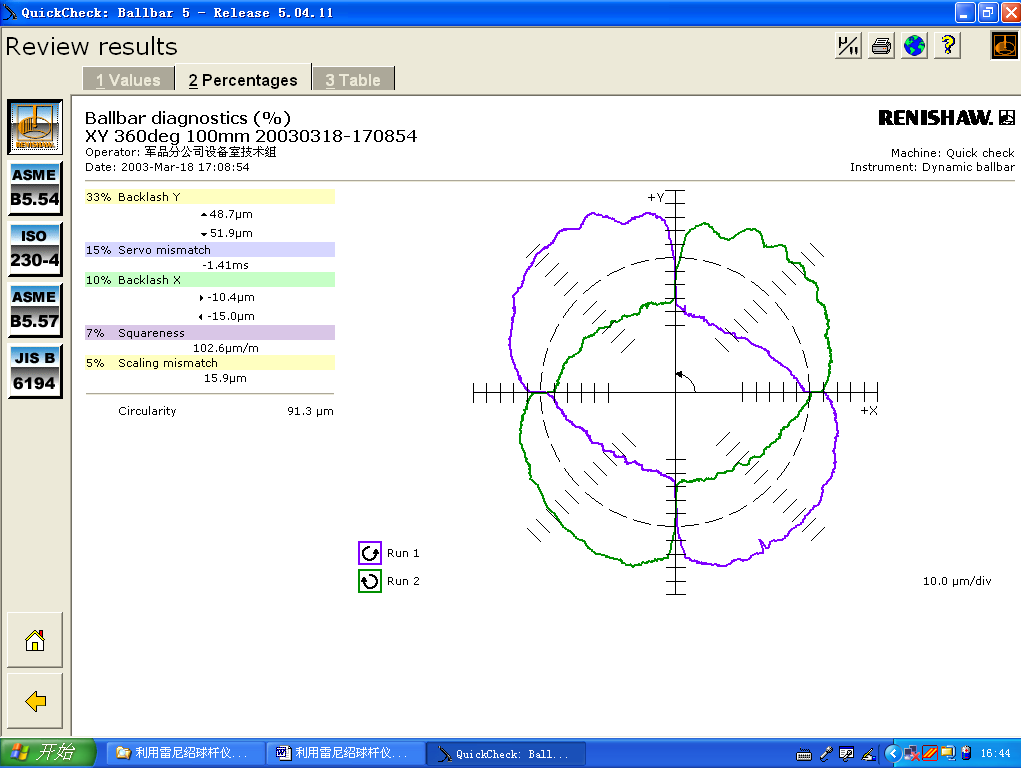
When the accuracy of the machine tool is poor or the servo shaft bearing is replaced, the machine tool needs to be detected and adjusted by corresponding instruments, such as Renishaw ballbar, laser dual frequency interferometer, etc. The detection and adjustment method of A2100 system machine tool is basically the same as that of other machine tools. For details, please refer to the documents of corresponding detection instruments. After detection, the modification of backlash and pitch compensation parameters is completed in the System Configuration/Error Compensations/Bi-directional Axis Comp page.
5 Repair of other faults
This involves tool changing, electric cabinet circuit, etc. The last example shows that repair sometimes goes through a lot of repetition, but as long as the principle and thinking are clear, and the diagnosis and maintenance resources provided by A2100 system are well used, the most difficult problems can be solved.
Ex. 20 A SABRE1000 gave an alarm, which means that the system needs 10# tool, but the tool magazine turned to 9# position, and the actual observation shows that the current tool position was 12#. According to the operator’s reflection and some observation, found that the disorder was irregular and sometimes normal.
The machine tool adopts a hanging disc type tool magazine. The rotation of the tool magazine is driven by an ordinary single-phase motor and counted by a proximity switch. It was suspected that the proximity switch was faulty. During the inspection, it was found that the tool change of the machine tool had become normal. It is estimated that the proximity switch was dirty or loose.
Ex. 21 A SABRE1000 gave an alarm:
Alarm 39-28
Draw bar not clamped
Cause: the spindle draw bar is not clamped.
Remedy: check the air pressure supplied for the draw bar, and test the action of it with the button Draw Bar Unclamp on the manual pendent.
Confirm that the door of the working cabin is open, and select the Tool Setup function on the pendent. The correct solenoid/proximity switch signal is as follows:
SL_TL_CLMP high when the draw bar clamped, and low when loose
SL_TL_UNCL low when the draw bar clamped, and high when loose
PR_TL_CLMP high when the draw bar clamped, and low when loose
PR_TL_UNCL low when the draw bar clamped, and high when loose
Check the compressed air first, during which It was found that the proximity switch PR_TL_UNCL did not function. Moved it up about 0.5mm, and the machine became normal.
Ex. 22 A VMC1000C had the following alarm:
Alarm 44-43
Unable to communicate with unused channel
Cause: feedback signal of unused servo channel cannot be detected. This is usually because the encoder in the channel is not configured or installed.
Remedy: install loopback plugs in all unused servo channels.
During the repair, it was found that the servo board and I/O board were wrongly inserted, and the alarm disappeared after the exchange.
Ex.23 The QF16 jumped off when a VMC1000C moved Z axis. According to the circuit diagram (omitted), QF16 is the 110VAC power supply protection switch for Z axis brake. 110VAC is applied to both ends of the brake coil after full bridge rectification, and the protection diodes V1 and V2 are connected in series with the coil in parallel.
It was found that a solder joint of the brake coil had worn through the isolating sleeve and touched the metal end cover inside the motor, causing a short circuit. Re-welded, improved the isolation and replaced the damaged V2 with a 24V voltage stabilizing tube BZX85C24 (1N4749).
It is worth noting that before dismantling the Z axis motor, the spindle must be supported by wood blocks or other things, otherwise the spindle WILL slide fast to the workbench after dismantling the motor!
First, disconnect the Z axis motor from the lead screw for debugging. Note that the motor will ROTATE or JUMP when adjusting the position of the revolver. Hold it carefully by hand! Adjust it bit by bit and fix it after adjustment. (No. 44-45 alarm will appear during adjustment, meaning Z axis servo failure, which will be automatically eliminated after adjustment.)
Installed the adjusted motor back to the Z axis. The Z axis could now move normally, but when it returned to the reference point, the following alarm appeared:
Alarm 44-6
Z axis grid alignment error
Cause: Z axis grid alignment has been completed, but no mark pulse is found.
Remedy: check encoder, wiring and mark pulse settings. The mark pulse setting is in the axis data of the servo configuration. Index Invert A and Index Invert B should be set correctly, otherwise the mark pulse is not easy to find.
On the Configuration/Machine Application/Z AXIS page, adjusted the value of Move To Align Zone (generally between -4 and 4). Finally, when it was adjusted to -3, the alarm was eliminated.
After properly adjusting the Z axis limit, on the Configuration/Machine Application/AUTO/MAN TL CNTL Z AXIS page, modified the value of TL Store 1 Auto TL Chg Pos item (this example was finally changed to +564.3000mm), executed T1M6, T2M6 and M30 commands under MDI to adjust the tool change point.
Now the machine run normally.
Ex. 24 After a SABRE1000 spindle dropped down and crashed on the machining part, all three driving belts were broken, and the spindle orientation needed to be adjusted after replacing the belts.
It needs to be adjusted separately in automatic mode and MDI mode.
Through adjusting the belts and repeated tests, the spindle orientation adjustment under the automatic mode was performed. When adjusting, put the tool magazine disc close to the spindle. On the Mchine Application/Runoff-Service page, Tool Changer Setup, check Spindle TC Posn, and slowly lower the spindle with the pendent to observe the orientation angle value.
The VFS5 spindle module can also be adjusted by serial communication with an external laptop:
1 Power on, run MotionLink, baud rate automatically set, after successful serial connection the = = > prompt appears
2 B↙ (single arrow appears)
3 LOCK■OFF↙ (open parameter, ■ denotes space, the same below)
4 2100↙
5 P■P1↙ (see the actual position of the current spindle)
6 Turn the spindle to the correct orientation position by hand and record the value (P1)
7 P1■ (the value of P1)↙
8 RUN↙
9 LOCK■ON↙ (close parameter)
The orientation adjustment in MDI mode can be completed by changing the value of the Spindle Orient Position item on the Configure/Machine Application/Spindle Range1 page.
Ex. 25 When a SABRE1000 spindle returned the tool to magazine, an alarm appeared:
Alarm 39-76
Spindle orientation error during tool change
Cause: the spindle cannot be oriented to the tool change position
The spindle driver did not set the input signal CR_OR_Comp. The software has made five attempts to orient the spindle driver correctly.
Remedy: correct equipment status:
Input CR_OR_COMP set
If it is a high torque spindle, then
PR_C_TPA needs to be set when M_ACT_DRUM = 1
PR_C_TPA needs to be reset when M_ACT_DRUM = 2
Output CR_SPDL_ORN or CR_SPDL_ORN2 set (not at the same time)
Note: CR_SPDL_ORN2 is only applicable to the spindle orientation of the second tool magazine (option) of ARROW series machine tools.
Check the spindle drive setting and adjust the offset in the system.
In case of high torque or 125000 RPM spindle, check the connection cables between PR_C_TPA switch to A2100 and spindle driver.
If the spindle driver is KOLLMORGEN VFS5, check, with MotionLink, feedback from PR_C_TPA to the spindle driver and view the value of the HOME signal. When the input is reset, it should be level 0, and when the input is set, it should be level 1.
First checked CR_OR_COMP signal, was reset state. Then observed if the relay corresponding to CR_OR_COMP signal acted when trying to change the tool, did not. Used a multimeter to measure the potential voltage at the O3 end of the spindle module (pin 43 of the C8 plug), during which it was found that CR14 acted. Therefore, after cleaning the C8 connector, the machine tool worked normally.
Ex. 26 A SABRE1000 had a red alarm, which means that the real-time processing has timed out. After disassembling the right main board, it started normally. However, when executing the program, it should grasp 1# tool, but it became 5#. The same phenomenon persisted for three times.
Due to the good repeatability of the fault, the factors such as the proximity switch of the tool magazine disc and the brake of the magazine motor can be eliminated.
The tool table was as follows:
Pressed the Data Reset key on the pendent, the “0” in the above table became “5”, and changed it to “1”, and the machine returned to normal.
Ex. 27 A SABRE1250 could not be powered on, and there was no alarm. Looking at the circuit diagram, the power on circuit is completed by the normal operation of ESR1 (K1, K2, K3 contacts are all closed) of the emergency stop relay (combination), and the abnormal operation of any point in the branches composed of the emergency stop switchs (main console, pendent, chip conveyor, etc.), the limit switch of each axis (X, Y, Z, etc.) and the door switches (left, right, etc.) will destroy the normal operation of ESR1. It makes the machine power unable to be maintained, which means that the machine power cannot be on.
It was judged that ESR1 was not working normally by the indicator light on ESR1. The potential of each point of the branch was measured point by point with a multimeter (the reference point is the T21 end of ESR1). It was quickly found that the switch of the left door was not closed. The accumulated aluminum chips were stuck in the crack of the door slightly and deformed it. After cleaning, the machine tool returned to normal.
Ex. 28 A VMC1000C had the following alarm:
Alarm 42-11
APC Start Fail
Cause: This is an internal error. The Programmable Controller failed to start because of the following error:
Hardware Configuration Table Error.
Returned by: cr_build_hwct.
Cause: A board with an unrecognized board ID is plugged into a rack.
Remedy: Turn the power off and on again. If the problem persists, try reinstalling the system. Call your service representative.
Replaced the hard disk with the backup, and the fault still existed.
Pulled out and pushed in the right main board, and the alarm changed to:
Alarm 40-33
Output/Fuse Failure in APC Rack 0
Cause: A fault condition was detected in one or more of the output devices in APC Rack 0.
Remedy: Check for current overload, excessive temperature or the external power source. If possible, correct the problem and restart the control. If the condition persists call your service representative.
Exchanged the right main board with that of a SABRE1000 to test the machine. The result showed that the machine was normal, but the SABRE1000 gave the same alarm. Later replaced the right main board with a new one, the machine returned to normal.
Ex. 29 A SABRE1000 had a serious fault. After testing and repairing all six servo modules (X, Y, Z, A, spindle and power supply), installed them again, checked all fuses and possible short circuit, and then tested the machine.
After the self-test of the system was completed, 40-33 alarm appeared (see the above example for the meaning). Found two copper foils were burnt out after checking the output board. One of them is the connection from +24V to the I/O board. Recovered them by wires. But the machine tool could not be powered on and there was no alarm.
Replaced the I/O board, 39-6 alarm came (see Ex. 16, Cause 1), checked the circuitry from +24V to the pin 32 of the plug J1 (CR_AXES_RDY), normal. After carefully observing the startup process, it was found that after pressing the startup key, the Drive Ready indicator of Y or Z axis module was on, while the X axis was not, and an alarm appeared after a few seconds.
The X and A modules were then sent for inspection and maintenance, and then installed back into the machine tool. The Y, Z and A axes now could be moved, but the X still could not. Each axis could move normally after X module being sent for repair again.
When the magazine returned to zero, it was interrupted by a proximity switch alarm. Four proximity switches related to tool change were replaced, and the magazine return finished.
After replacing the four coil protection diodes and sending the spindle module for repair again, the machine tool basically returned to normal. After the spindle orientation adjustment, the machine tool was fully available.
The machine tools of Vickers A2100 system have been used for more than 20 years. If the failure rate is too high, the system can be replaced by others, such as FANUC 0iF, Siemens 828D, etc.