0 Introduction
Helitronic Power CNC tool grinder is equipped with Kraft & Bauer FB703 fire extinguishing device. Due to the lack of technical documents, most operators do not know much about it. So not only can it not play well its function, it will bring inconvenience to the machining. This paper attempts to help solve these problems.
1 Basic working principle
The Helitronic Power CNC tool grinder and its fire extinguishing device are shown in Figure 1.

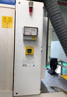

Fig.1 Helitronic Power CNC tool grinder and its fire extinguishing device
The distribution of fire extinguishing device in the machine tool is shown in Figure 2.
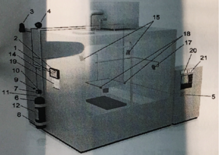
Fig.2 Distribution of fire extinguishing device in machine tool
1 Alarm and control set FB703 2 Fire extinguisher control FB703 with lockable clear glass door 3 Warning light 4 Siren respectively piezohorn 5 Manual alarm box (manual release) 6 CO2-container 7 Instaneous release valve 8 CO2-container holding 9 Pluggable pyrotechnical pressure gas generator 10 Valve covering 11 At transportation: valve hood, locking pin and lock nut 12 Container label 14 Extinguishing circuit 15 CO2-bucket spray with baffle pot 17 Visual game alarm 18 Automatic maximum detector 19 System label 20 CO2-warning label 21 Indication label “UV-or IR radiation”
After the fire extinguishing device is installed and debugged in the machine tool, it is automatically controlled by FB703 controller, and the operator does not need to intervene. Its working principle is as follows:
When the machine tool is powered on, the fire extinguishing controller FB703 (1) automatically initializes. After it is stable, it detects whether there is smoke, fire and other fire situation through the ultraviolet and infrared detectors (18). If there is, it gives an alarm through the alarm (3, 4, 17). If the fire still exists after a period of time (settable), it triggers the action of the solenoid valve (7) to open the CO2-container (6). Through the fire extinguishing gas path (14) and the bucket spray head (15), the carbon dioxide is ejected, causing the internal combustion engine to extinguish because of the lack of oxygen.
At the same time, the controller also gives the electrical signal to the machine tool, which is used for alarm, door closing, power off and other operations. The wiring diagram is shown in Figure 3.
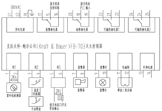
Fig. 3 Wiring diagram of fire extinguishing controller in machine tool
In case of short circuit, open circuit and other faults at the input end of the controller, the indicator light on the control panel will be on, and the alarm signal will be sent to the machine tool at the same time.
2 Use and maintenance
2.1 Use
FB703 fire extinguishing controller panel is shown in Figure 4.
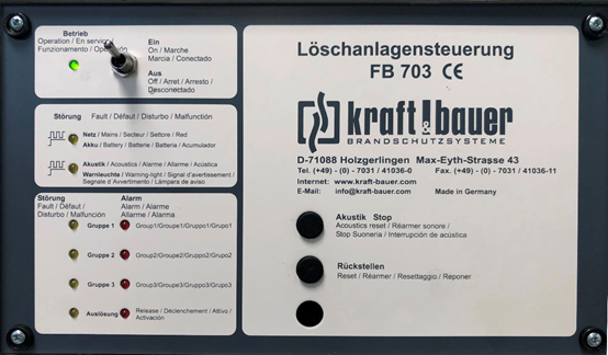
Fig.4 FB703 fire extinguishing controller panel
The control panel has a transparent glass door, which is locked by the key lock on the right. When the door is closed, a fixed bar on the door touches the switch at the bottom of the panel to give the close signal to the controller. When the door is open, the controller will alarm and give the machine control system (FANUC 310i) a signal indicating that the fire extinguishing system is not ready. The system gives alarm information and stops operation:
(G.0/N.2183) FIRE EXTINGUISHING SYSTEM NOT READY
(G.0/N.2048) no errortext found
The panel is divided into four areas with block faces. Except that the name, model, manufacturer and contact information of the controller are indicated in German in the right area, the other switches, buttons and LED indicators are marked in German, English, French, Italian and Portuguese languages, which makes people feel dazzled and unable to grasp the exact meaning. Actually, can just pay attention to the second (English).
2.1.1 Significance and function of operation and indication elements
2.1.1.1 Operating elements
Switch “On/Off”: normally in the open position, when closed, the machine will generate alarm and cannot work.
Key “reset”: clear the alarm and make the controller in a ready state. Press for more than 5 seconds.
Key “Acoustic stop”: when the controller fails or detects fire, an audible alarm will be given. Press this button for more than 5 seconds to stop the sound alarm.
2.1.1.2 Indicating elements
Indication “Operation”: this light will be on when the controller is powered on.
“Malfunction System/Accumulator”: flashes when external power supply fails; It will always be on when the internal battery fails.
“Malfunction Acoustics/Warning light”: flashing when the circuit of external piezohorn fails and continuously on when the external warning light fails.
“Malfunction Group 1-3”: when there is a short circuit or open circuit in the three groups of circuits, the corresponding lamp will be on. Press the reset button to clear after troubleshooting.
“Malfunction Release”: on continuously when the solenoid valve output is open and flashes when the glass door opens, the machine door switch circuit fails or the door is open.
“Alarm Group 1-3”: In case of an alarm on one of the three detector groups, this will be indicated by the corresponding LED. This display will be remained until the reset of the control.
“Release”: In case of an alarm this LED will be controlled parallel to the solenoid valve or the pyrotechnical pressure gas generator. During this time of extinguishing this LED will light constantly. After the finish of the extinguishing this LED will start blinking and remains recorded until the reset of the control.
2.2 Maintenance
It is divided into weekly maintenance, quarterly maintenance, three-year maintenance, four-year maintenance and post fire maintenance. The first two items are carried out by the operator, and the latter three are carried out by professional maintenance personnel or after-sales service personnel of the manufacturer. Due to the space limit, the specific content and method are not covered here. For more information, please refer to the reference [1] [2].
2.2.1 Weekly maintenance
Check whether the controller is in normal state and within the allowable time. Check whether the glass cover plate of the device is clean, and the power supply of the controller must be turned off during cleaning to avoid triggering the fire extinguishing process.
2.2.2 Quarterly maintenance
Check whether the fire extinguishing gas circuit, nozzle and solenoid valve are polluted or damaged, and whether the direction of the nozzle is correct.
3 Shielding
In many cases, because of the good environmental conditions, it is unnecessary to use the fire extinguishing device, or when the fire extinguishing device is difficult to recover in case of a fault, it needs to be shielded, otherwise the system will give an alarm, and the machine tool cannot function.
When the fire extinguishing controller is shut down or fails, a signal is sent to the input terminal X11.3 (FE-A1) of the PLC of the machine tool through the fault relay (terminals 18, 19), and the influence of the signal in the ladder diagram is shown in Figure 5.
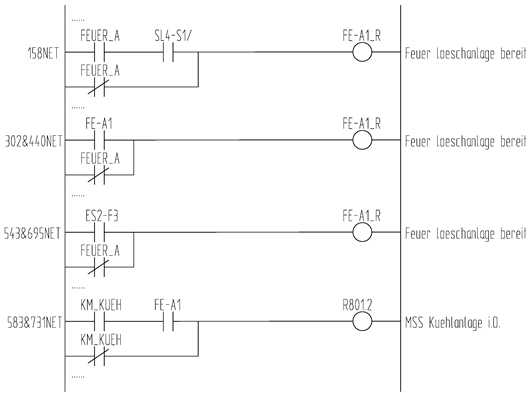
Fig.5 The influence of X11.3 (FE-A1) on ladder diagram
From the definition of PLC K parameters, K7.7 (FEUER_AN, Feuer loeschanlage angewaehlt) is the option parameter of fire extinguishing device. It can be seen from Figure 5 that if K7.7 is changed to 0, that is, normally closed contact FEUER_A is always on, the fire extinguisher ready signal FE-A1_R will always be 1, so the purpose of shielding is achieved.
4 Conclusion
By mastering the above contents, the fire extinguishing device can be used correctly to deal with various problems. However, the configuration is different on different machine tools. Please refer to the manual attached. If there is any unclear problem, please consult the machine tool manufacturer or agent in time.
Reference
1 Fire-extinguishing system,Walter Körber Schleifring
2 Local application extinguishing system FB 703, Kraft & Bauer