Linxin Sci-Tech
Analysis of VFS5 Main Program
The analysis of the flow chart of the main program is as follows:
2080H-2092H:
After power-on reset, N80C196KB16 starts at 2080H.
First, write zero to the output lines O1-O8 (ULN2803A, 28) of the servo module VFS5.
2093H-2096H:
Set the stack to 8000H-82FFH.
2097H-20B0H:
Check whether the parameter LOAD (RAM:F762H) is 1, and if 1, the user program that is solidified in ROM is loaded to the external RAM, of which the starting address is 8300H (the external RAM address space is 32K, that is, 8000H-FFFFH). The so-called loading is actually a copying of the user program stored in ROM to RAM, which copies the content of 4D6AH-5D09H in a total of 4000 bytes in ROM. In this VFS5 module, the actual location of the user program is 4D6AH-5B41H, with a total of 3544 bytes. Then check the number of characters of the program (not more than 20000) and fix it, the number of program instructions is stored in D130H, the address of the offset of the end byte FFH to 8300H is stored in D132H, the program’s character ASCII value sum (discarding those higher than two bytes) are stored into D676H (PGMCKSUM) and D128H-D126H’s two lower bytes. D129.7 is used as the flag bit. “1” indicates that the program is wrong, and “0” normal.
If LOAD is 0, the process is dropped. In fact, the contents of external RAM (DS1230Y-120) will not be lost after power-off.
Then the program jumps to 0100H.
0100H-0125H:
Add all the bytes of 0100H-7FFFH (except 1FFCH-1FFDH) in the ROM to see if the sum is equal to the content of 1FFCH-1FFDH (8626H). If not, it goes into a dead loop, and the CPU LED flickers to indicate firmware errors; if equal, it lights up the CPU LED and then executes the program down.
0126H-0134H:
Check whether the setting of revolver resolution RDRES (manufacturer set, stored in the external data memory D6B9H unit) matches the hardware. If so, give information 199 (DRIVE POWERED UP). Otherwise light the FAULT LED, and put the No.27 message (R/D JUMPERS) into the buffer.
0135H-0177H:
Initialize parameters, reset outputs, etc., such as setting the servo motor as induction motor.
Initialize parameters, reset outputs, etc., such as setting the servo motor as induction motor.
0178H-017AH:
Check the variable BAUD to see if it is among the values of 300, 600, 19200. If it is, be ready to receive. If not, try to autobaud and flash CPU LED. The attempt maintains until success. The setting of ABAUD switches between checking and direct autobauding. FAULT LED turned OFF within this subroutine.
Check the variable BAUD to see if it is among the values of 300, 600, 19200. If it is, be ready to receive. If not, try to autobaud and flash CPU LED. The attempt maintains until success. The setting of ABAUD switches between checking and direct autobauding. FAULT LED turned OFF within this subroutine.
017BH-0194H:
(to be continued…)
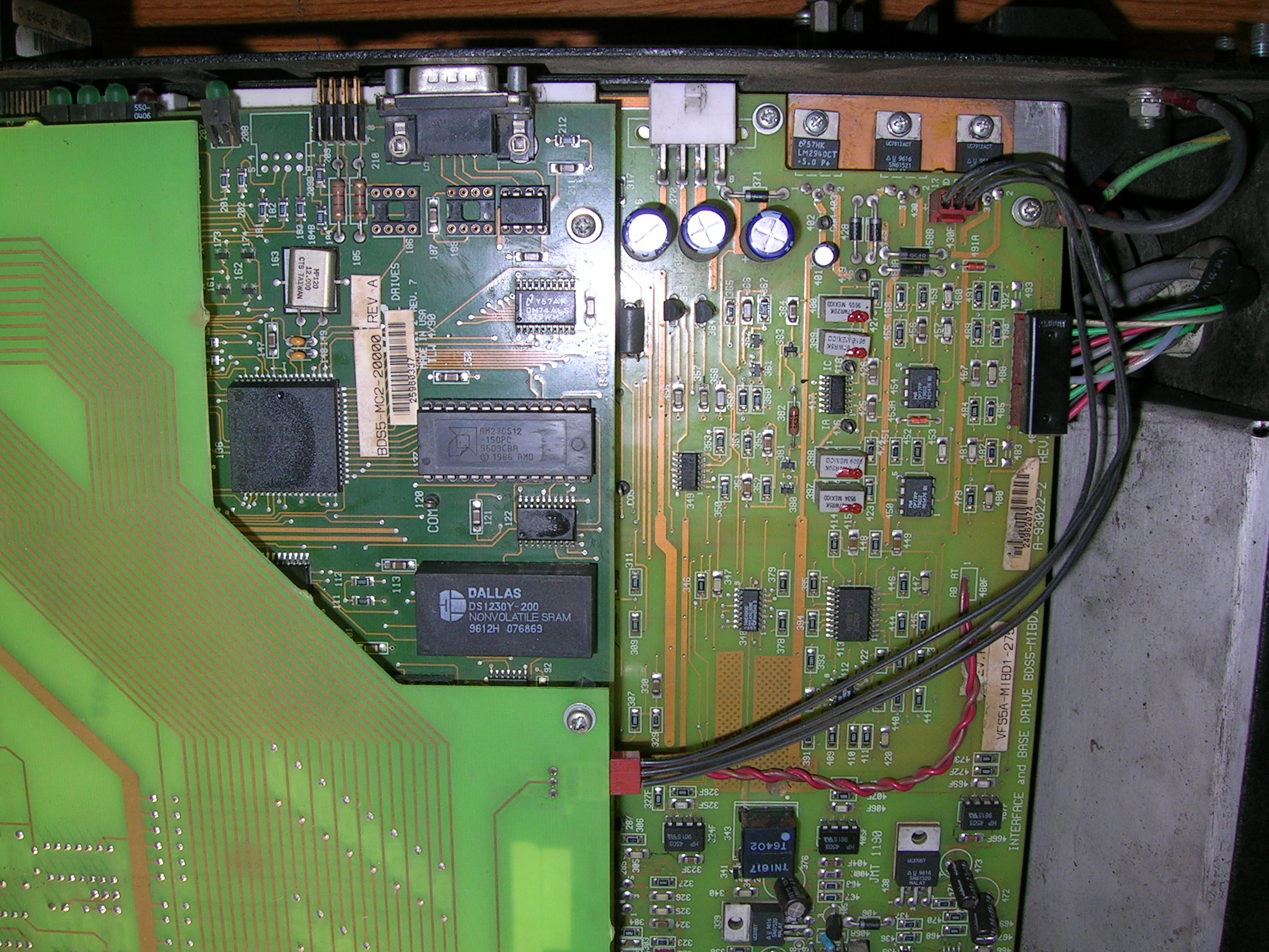
VFS5 System Program Disassembled
Data Sheet of Main IC Chips
VFS5 Spindle Drive Manual
Here are the manuals. Understanding the use of this module helps to understand its principles.
VFS5 Main Program
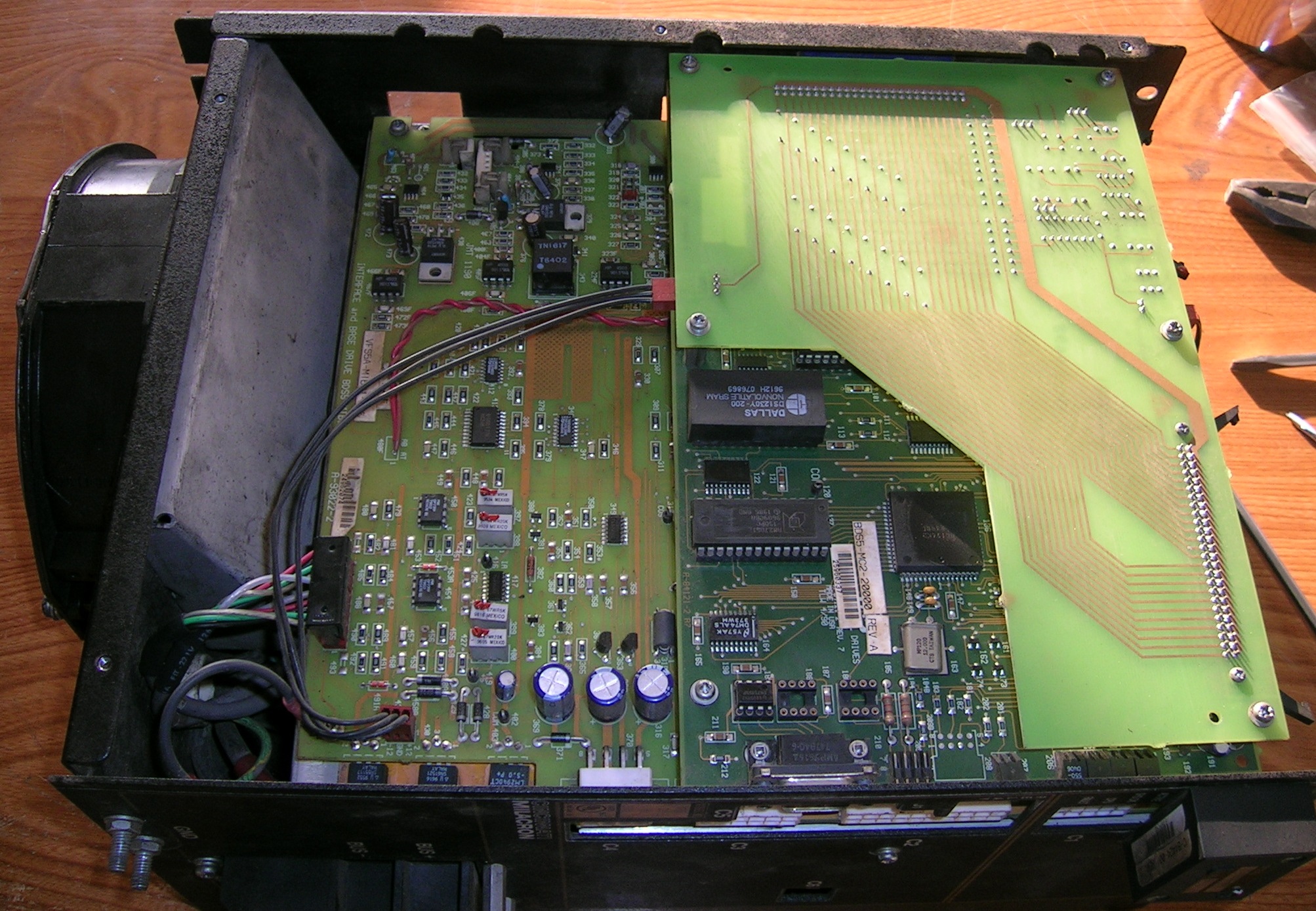
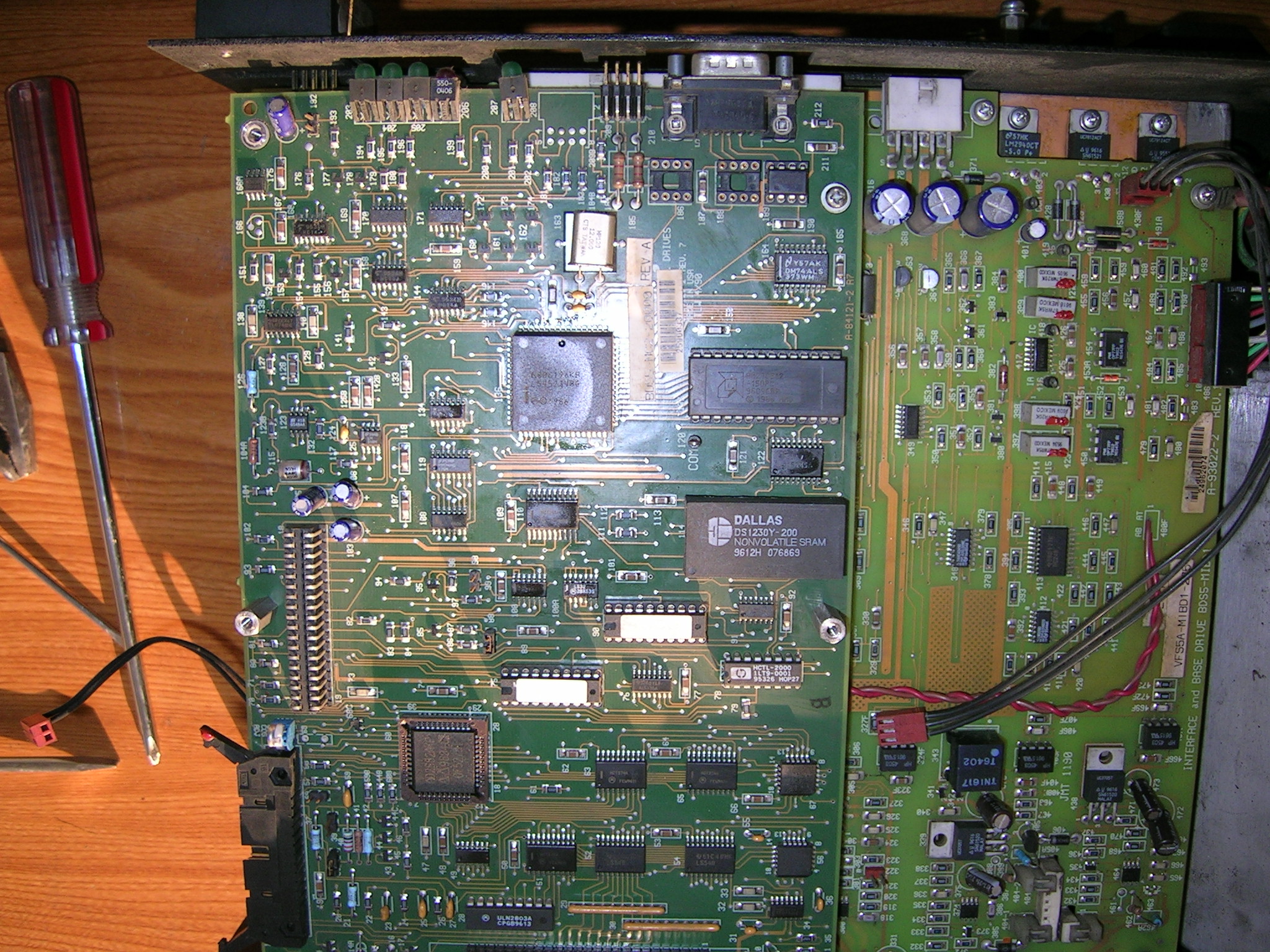
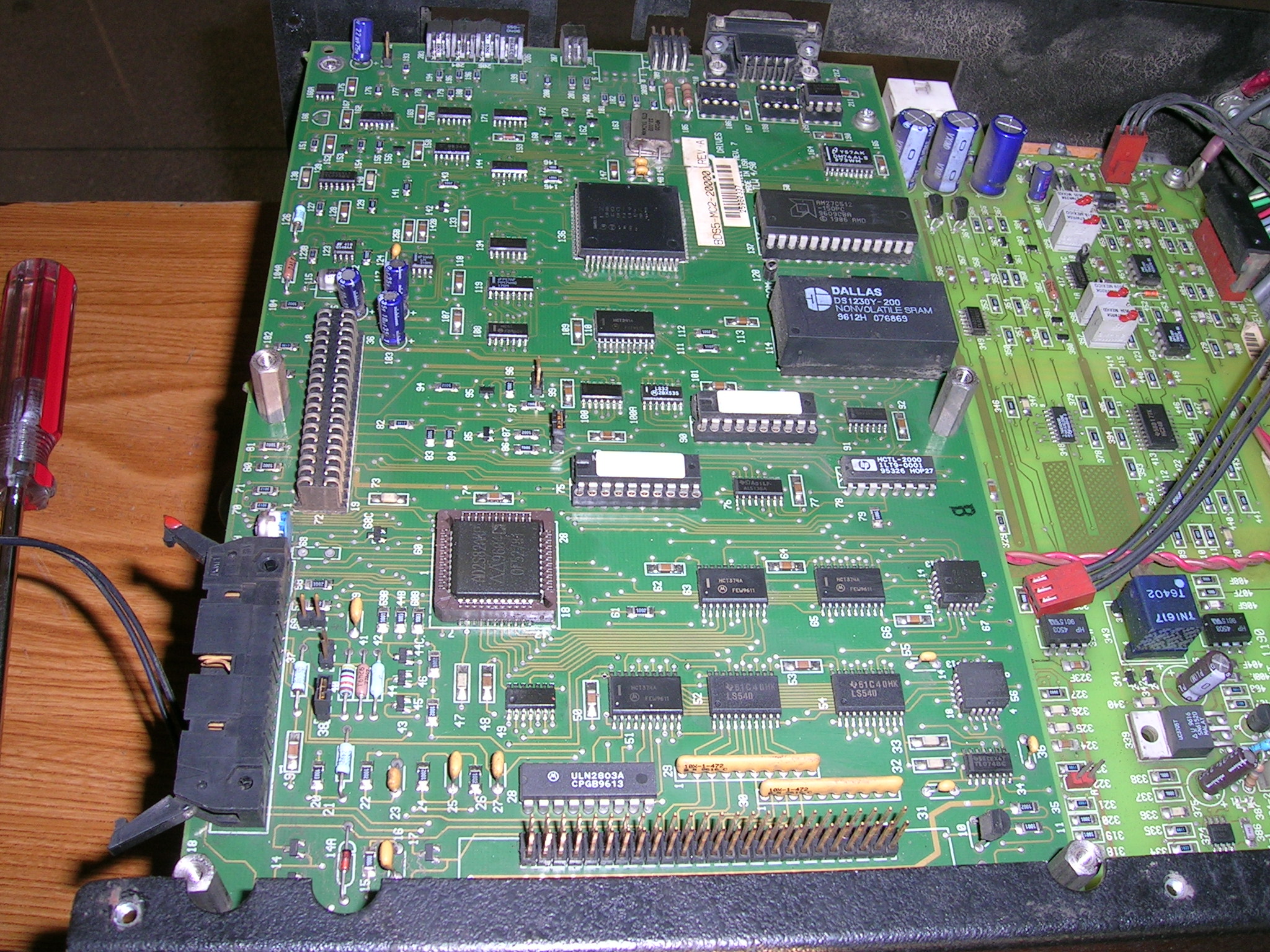
From the circuit diagram, it can be seen that the core of the VFS5 spindle module is the MCS-96 Series MCU or micro controller N80C196KB16(136) of Intel company, with a small amount of RAM in the chip, but without ROM, it usually needs external expansion. The module uses AM27C256(137) and DS1230Y-120(114) as external program and data storage, and the memory space is 32K, respectively. AM27C256 has no security byte, and programmers can read the code directly. The N80C196KB16 fetches code from the address 2080H after reset, It is easy to obtain the assembly language program by disassembling code from the address. Then the control flow chart can be drawn (see below).
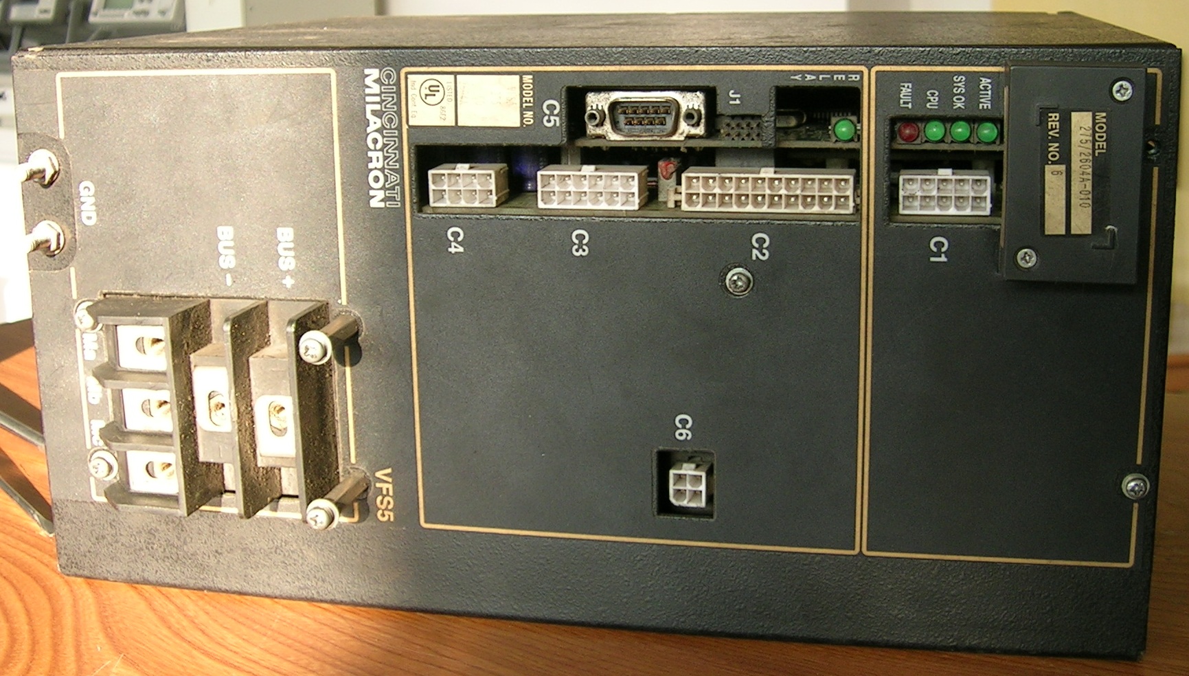
Circuit Diagram of VFS5
Due to the limitation of the website, we can only provide PDF schemas in the case of ensuring the clarity. If you need other formats, such as RAR, PNG or SCHDOC, please leave a message to inform the e-mail address.
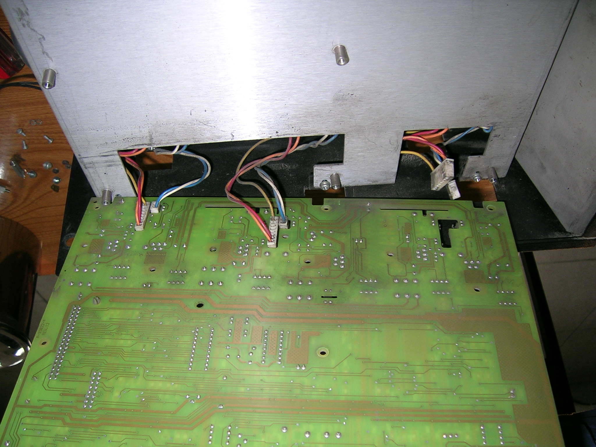
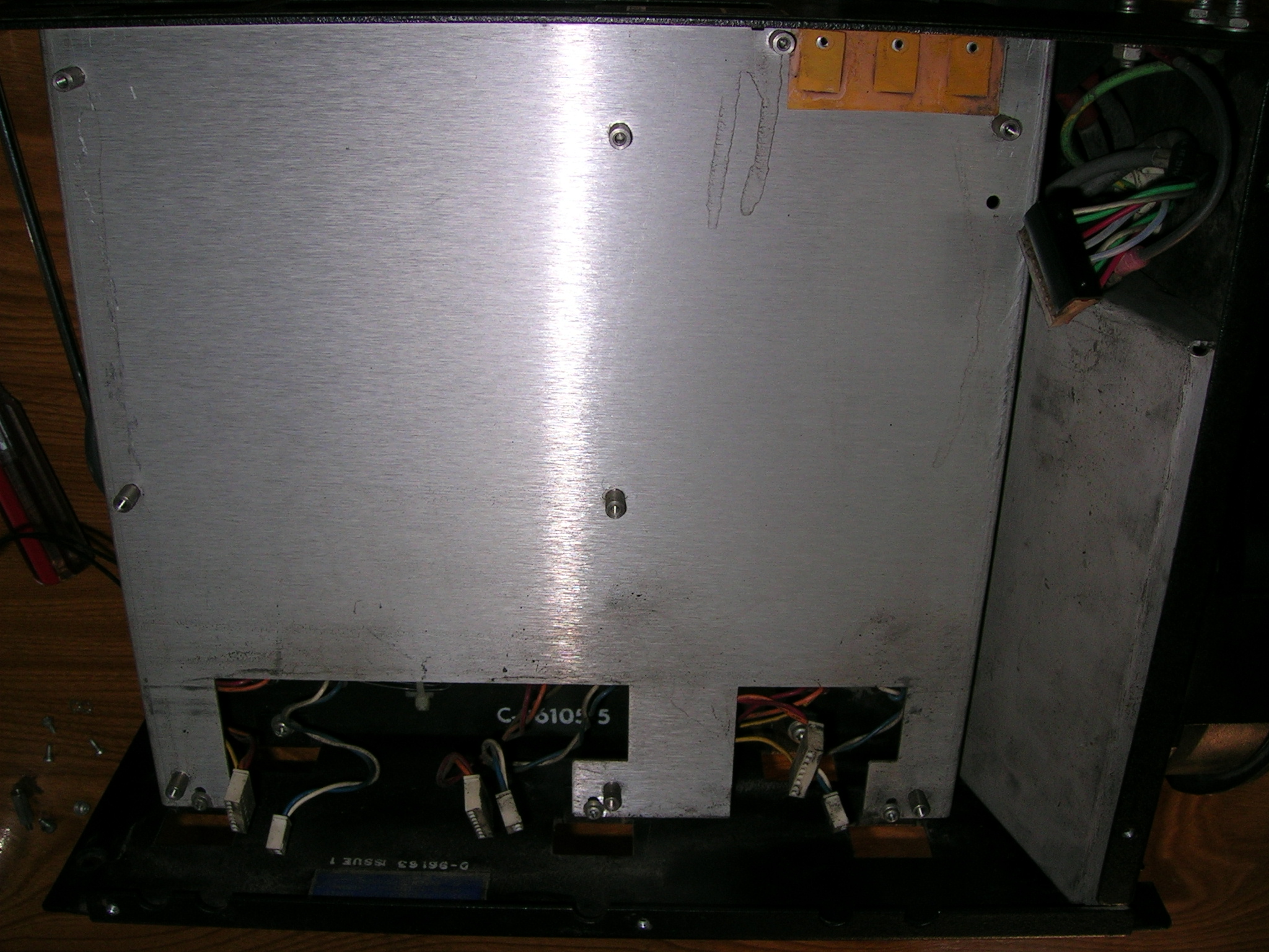
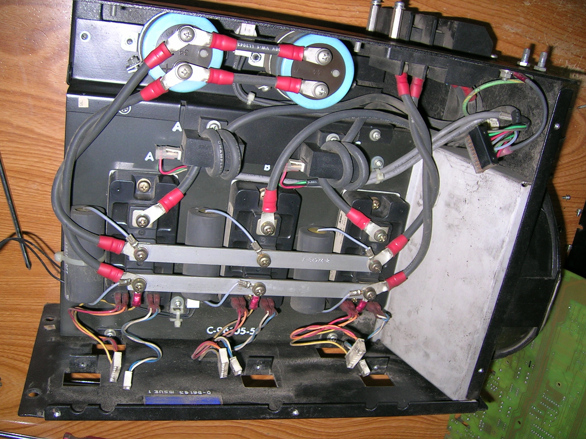
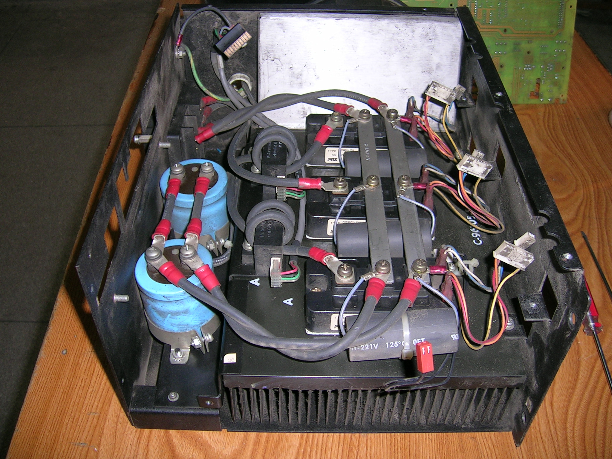
A brief introduction to the spindle servo module VFS5
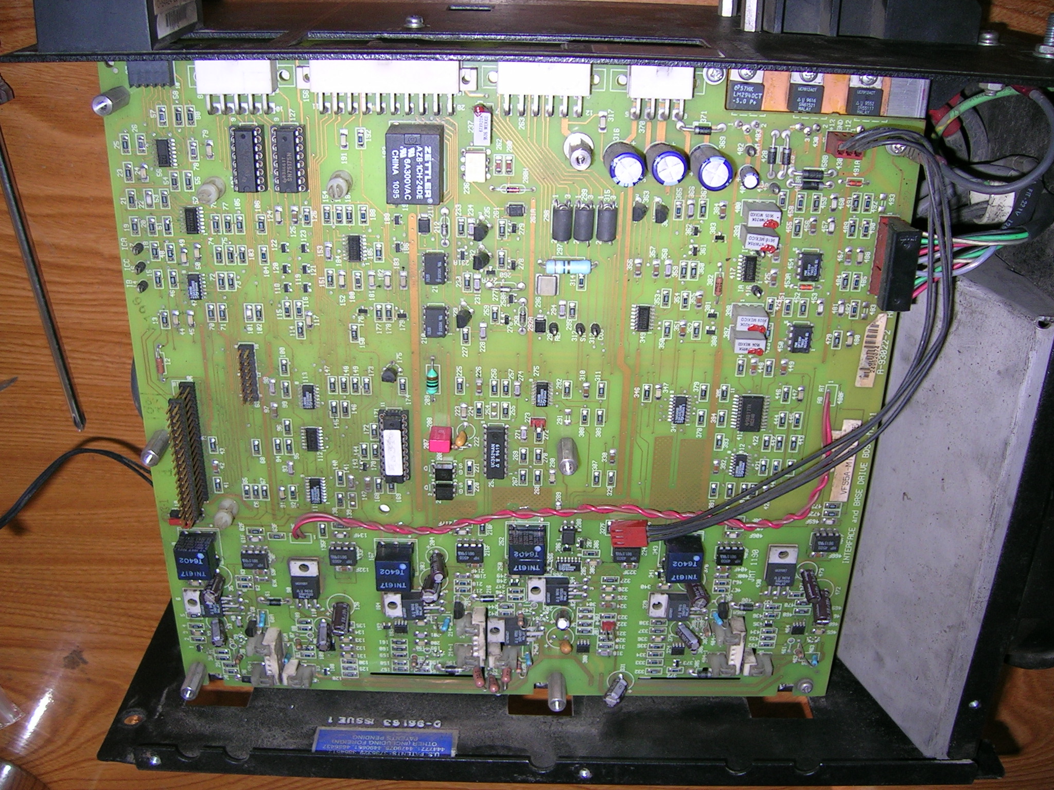
The spindle servo module is the most complex, and VFS5 is an improved type of BDS5.


A brief introduction to the system
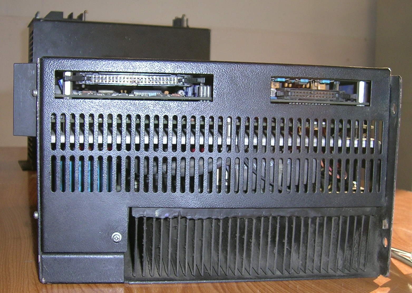
The Kollmorgen BDS4/5 servo system is a product of 90s, which is usually composed of power supply, moving axis and spindle modules.

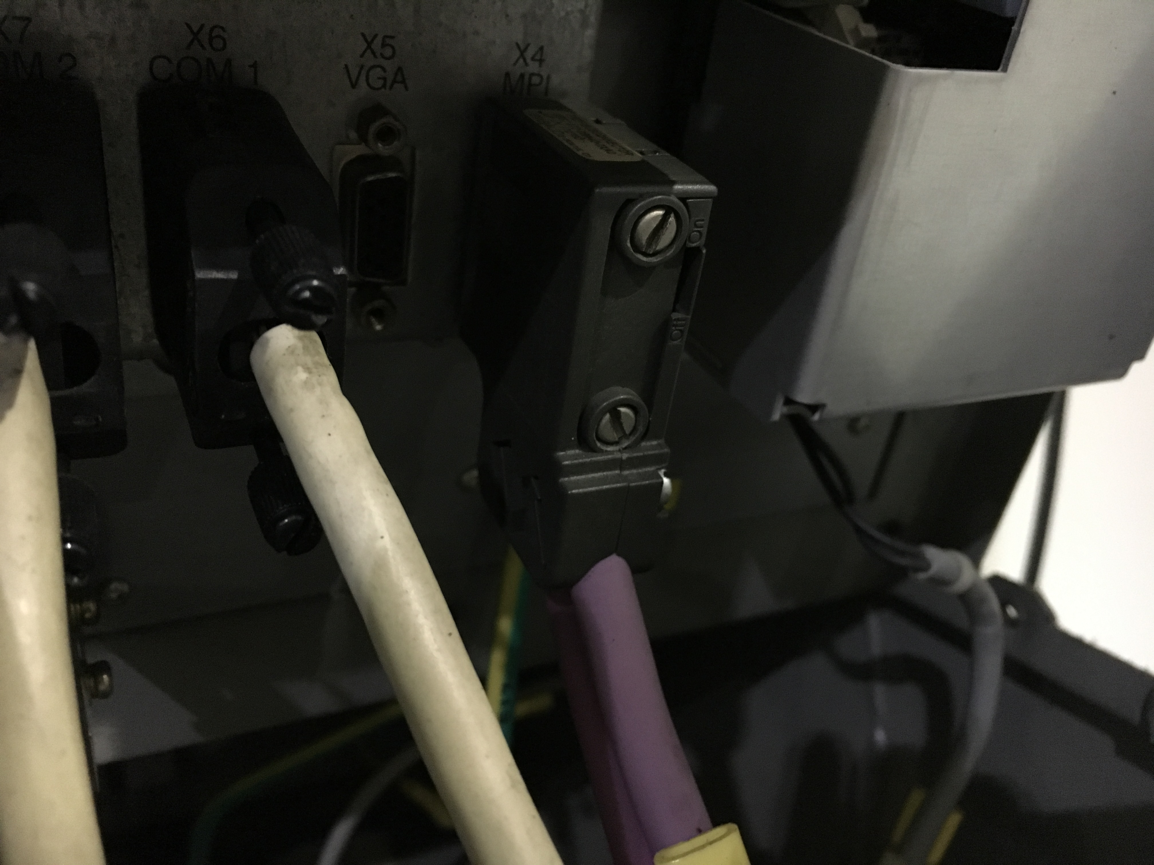
Alarm 120201 (Communication interrupted) & 120202 (Waiting for connection to NC)
Fault:
Alarm 120201 (Communication interrupted) came randomly and frequently. Sometimes it turned to be 120202 (Waiting for connection to NC).
Remedy:
The information on the 840D diagnostic manual is as follows:
120201 Communication interrupted
Definition
The operator panel is connected with the NC and PLC via a serial bus. This alarm occurs if the communication to these components is faulty. Together with this alarm, all display values connected with NC/PLC become invalid. Such malfunctions are normal during startup of the controls (e.g. after reset).
Reaction
Alarm display.
Remedy
The alarm disappears automatically as soon as the error situation is terminated. If this alarm is pending permanently, this may have very different error causes (e.g. cable break, no startup of NC/PLC, incorrect address/baud rate configuring of one of the bus nodes etc.).
120202 Waiting for connection to NC
Definition
The operator panel is connected to the NC and PLC via a serial bus. This alarm occurs when the MMC is started up for the first time if the NC/PLC power-up is not yet complete, or if an error occurs during communication between these components. All display values associated with the NC/PLC are rendered invalid by this alarm. Such malfunctions are normal during startup of the controls (e.g. after reset).
Reaction
Alarm display.
Remedy
The alarm disappears automatically as soon as the error situation is terminated. If this alarm is pending permanently, this may have very different error causes (e.g. cable break, no startup of NC/PLC, incorrect address/baud rate configuring of one of the bus nodes etc.).
It can be seen that the failure of the machine is probably caused by the poor condition of the bus line between MMC and NC (purple) or connectors. After removing, re-inserting and fixing the plugs the alarm disappeared.
If it does not work later, can try cleaning the connectors or replacing the line.
If it does not work later, can try cleaning the connectors or replacing the line.